Fiber Bragg gratings (FBGs) couple a relatively small amount of propagating light from the core of the optical fiber into the cladding. This conduct is referred to as cladding mode coupling. The light coupled into the cladding will progressively be lost in the cladding as the propagating energy moves along the fiber. In practice, the level of the cladding mode losses limits the maximum number and spectral proximity of the FBGs on the same fiber.
The effect of cladding mode losses is revealed in the transmitted spectrum of an FBG, where a ripple or dip occurs at the shorter wavelength side of the Bragg peak [1], as shown in the examples below.
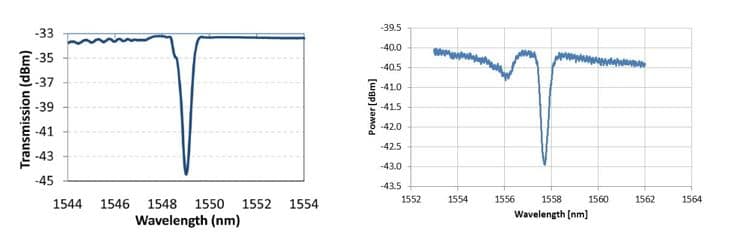
The size of these losses depends on the type of inscription of the FBG to be considered. For draw-tower gratings (DTG®s), the effect is relatively low. For femto second gratings (FSGs), the effect can become relatively larger, depending on the inscription method. As an example; an FSG array of 5 Bragg wavelengths (peaks) inscribed by a Point-by-Point (PbP) technique exhibits a typical reflection and transmission spectrum as shown in the figure below.
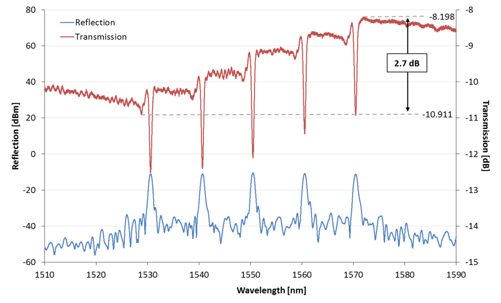
The transmitted spectrum reveals a stepwise incline of about 2.7dB, which reflects progressive incremental cladding mode losses, affecting pre-dominantly the Bragg gratings with the shorter wavelengths.
The presence of cladding mode losses can lead to FBG cross talk, as shown in the picture below. For this test, the array from the above figure (chain of 5 fiber Bragg gratings inscribed using FSG-PbP technology) was connected from the longer wavelength side to the interrogator, while the third grating was being strained (Bragg wavelength shift up to 3200 pm). Each graph was given a fixed offset in the y-axis to show the relative performance and for the sake of clarity.
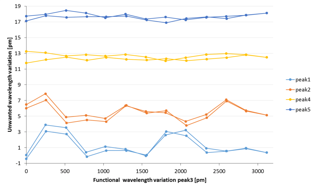
The signals from the longer wavelength gratings (peak4 and peak5) exhibit better stability, whereas the shorter wavelength fiber Bragg gratings (peak1 and peak2) exhibit more instability as cross talk. This effect can be traced back to the cladding mode losses of the third grating (peak3), which influences the spectra of the first and second FBG and leaving the spectrum of the fourth and fifth grating unaffected.
It is clear that cladding mode losses can deteriorate the multiplexing possibilities of fiber Bragg grating technology. However, part of these cross talk effects can be mitigated by interrogating the sensors from the shorter wavelength side. .
For more details, please contact us on info@fbgs.com
[1] T. Erdogan, “Fiber Grating Spectra”, Journal of Lightwave Technology, vol. 15, no. 8, pp. 1277-1294, 1997.