Lead-in/out fiber marking and wavelength indication
As of January 2017, FBGS released an improved protocol for marking the lead-in and lead-out of the Draw Tower Grating (DTG®) fibers.
If the serial number of your DTG® fiber starts with PR2017_03 or higher, please use the following identification scheme:
The fiber end next to the lowest Bragg wavelength (lead-in) is indicated by 3 groups of 8 narrow-spaced black markings as in the figure below:
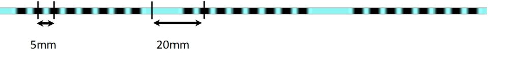
The overall length of the lead-in marking section is about 150mm.
The fiber end next to the highest Bragg wavelength (lead-out) is indicated by 2 groups of 8 widely-spaced black markings as in the figure below:
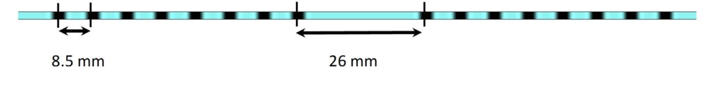
The overall length of the lead-out marking section is about 150 mm.
If the serial number of your DTG® fiber is starting with PR2017_02 or lower, please use the following identification scheme:
To identify the lead-in side (lowest Bragg wavelength) of the optical fiber, look for a continuous green ink mark, while a continuous red ink mark on the opposite end indicates the lead-out side (highest Bragg wavelength). A closer proximity to the DTG® with the lowest Bragg wavelength is indicated with a dashed green marking, while the DTG® with the highest Bragg wavelength is indicated with a dashed red marking as shown in the figure below. Similarly, for chains of same Bragg wavelength DTG®s, green and red markings correspond to the lead-in and lead-out sides.

In case of having short lead-in and lead-out lengths, the dashed lines are omitted. The lead-in side (before the DTG® with the lowest Bragg wavelength) is indicated with a continuous green marking, while the lead-out side (after the DTG® with the highest Bragg wavelength) is indicated with a continuous red marking as shown in the figure below.

DTG® Marking
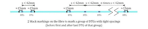
The DTG®s are individually marked by two (2) short black markings around each of the DTG®s with a spacing of approximately 30mm. This applies to a DTG®separation of greater than 62mm as shown in the figure below.

For a DTG® separation less than 62mm, the DTG®s are marked by a black marking approximately 15mm before the center of the first DTG® and a second black marking approximately 15mm after the center of the last DTG® as shown in the figure below.